
As used in Motor Show
without the optional extra +5VDC circuit.
As used in Dakar
with the optional extra +5VDC circuit.
|
|
| 1B11190 Power Supply As used in Motor Show without the optional extra +5VDC circuit. |
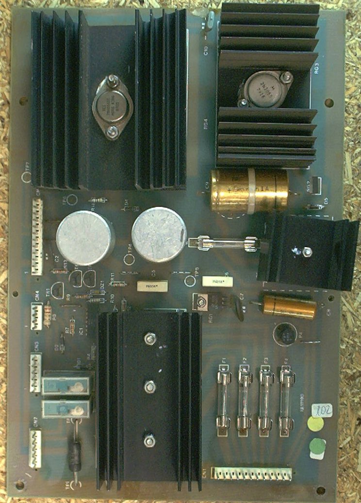
1B11190 Power Supply As used in Dakar with the optional extra +5VDC circuit. |
The power supply board takes the input voltage from the transformer in the main cabinet, and generates the +5, +12, -12, +39, and -5 voltages needed for the logic, lamps, solenoids, and display circuits.
The input Molex connector at the bottom right corner (CN1) of this board can overheat with time, scorching the housing and building up resistance in the connector pins. Check here for any signs of overheating and replace the connector and header as necessary.
The fuse clips used are cheap and tend to corrode and weaken over time. They are also a non-US-standard size. Replace all of the fuse clips with high-quality ones (like the ones Mouser sells as part number 534-3513). To do this, the board will have to be modified by drilling holes to mount the clips properly. The solder pads for the fuse clips are large enough to allow 2 x 1/16" holes to be drilled to allow a normal fuse clip to be soldered in place. Enlarge one hole on each side, and add one new hole to fit the new fuse clip in place.
There are three bridge rectifiers mounted under the large heat sink in the middle of the power supply board. If one of them fails, you should replace all three of them while you already have the board out and are working on it. Two of the three are lug-type bridges and require a soldering iron that can deliver enough heat to work a large joint. Don't try this with a 15W Radio Shack soldering pencil!
Before trying to troubleshoot a game in an unknown state, verify that the power supply is getting the correct input voltages and producing the correct output voltages.
Disconnect CN1 from the power supply board and test the transformer first. The correct way to test a transformer with a meter is to read voltages between pairs of pins in the connector. Do not attempt to read a voltage compared to the chassis ground, you will get approximately half the voltage reading that you would expect to see. Put your DMM on the appropriate VAC range before testing each pair of pins in this connector.
| Pin 1 | Wire Colour | Pin 2 | Wire Colour | Voltage |
|---|---|---|---|---|
| 1 | Red | 2 | Red | 15VAC |
| 3 | Brown | 4 | Brown | 10VAC |
| 5 | Yellow | 6 | Yellow | 10.5VAC |
| 7 | Blue | 8 | Blue | 43VAC |
| 9/10 | Green/Green | 11/12 | White/White | 6.5VAC |
Note: The 15VAC input is shown on the schematics, but is not used on Motor Show or Dakar. It seems to be there to feed the optional +5V circuit shown on the power supply board on the right, above, but that was not used for anything on Motor Show or Dakar. I do not yet know if Mac Attack or World Cup '90 used the optional +5V circuit.
After verifying the input voltages from the transformer, turn the power to the game off and reconnect CN1 to the Power Supply board. Disconnect the Molex connectors from the Power Supply that go to the Driver and Sound boards. Disconnect the ribbon cables from the CPU board that go to the Driver, Sound, and Display boards. Disconnect the Molex connectors from the CPU that go to the switch matrix. This leaves just the Power Supply and the CPU connected.
Turn the power on to the game, and the CPU should boot up (see CPU Startup). There are several test points on the Power Supply board to check:
| Test Point | Voltage |
|---|---|
| TP1 | Ground |
| TP2 | 5VDC |
| TP3 | 39VDC |
| TP4 | -12VDC |
| TP5 | Power Failure (note) |
| TP6 | 5.6VDC |
| TP7 | 5VDC |
| TP8 | -5VDC |
Put the black lead of your DMM on TP1, and use the other lead to probe these test points. On some boards, there are nice little wire loops soldered to the test points. On others, there are none. I have found that it is easier to test these with the loops, and have taken to installing them. You can use any scraps of 18 ga. wire, strip the insulation, and solder in place. Keep the loops short, no more than 1/4" tall.
Note:
The Power Failure test point is a logic level output of a LM339 at IC1 that shows whether the Power Supply is putting out correct voltages for the CPU board to boot up. It is tied to the reset pin on the CPU. The POWER FAILURE line inhibits the reset circuit from acting until the power has stabilized. There are two voltages being monitored via IC1.The LM339 uses the +12v filtered DC supply as a reference voltage. This is supplied at (B) in the schematics (IC1 pins 5 and 11). The first voltage monitored is the +12v, via a 5.6v Zener diode, to compare to the reference +12. The output of this controls transistor TR3.
The other monitored voltage, at (A) in the schematics, is used to control the transistors at TR2 and TR1. These three transistors (TR1, TR2, TR3), in parallel, control the POWER FAILURE line.
On the Power Supply schematics, (A) and (B) are the inputs to the LM339 on pins 4 and 10. Pins 5 and 11 are reference voltages. Outputs of the LM339 at pins 2 and 13 are controlled by comparing pin 4 / 5 and pin 10 / 11. The outputs switch the transistors TR2 and TR3.
On initial power up:
As the power supply stabilizes:
On the CPU board, POWER FAILURE comes in on CN9 pin 3 (Probably - this still needs to be verified). This allows the reset circuit to toggle the RESET pin on the CPU, which should boot and start running.
A voltage drop on the Power Supply board being seen by the LM339 would result in turning on TR2 or TR3, Grounding the POWER FAILURE line so that a LOW signal is sent to the RESET pin on IC9, forcing the game to reboot.
If you look at the schematics for the power supply, there is a +5V supply that doesn't seem to actually be used. On my Motor Show, that part of the board isn't even populated. On the Dakar, it's populated, but not connected to anything. I'm trying to figure out what they put this in there for. Maybe it was just something that they never used but had there for future expansion.
The schematics call for a jumper, J1, that connects the (+) output of bridge rectifier P3 to the output of bridge rectifier P5. I could not find any sign of this jumper on either of the boards pictured above. It is possible that this was added later, as the schematics I have are for a Mac Attack.