To make it easier to work on these boards on the workbench, instead of having to put them in a game to test them, it is possible to use a standard PC power supply and a few test jigs to test and diagnose them. There are no displays, since all visual output is via the monitor in the backbox, but at least some tests can be performed outside the game. For the most part, the boards only need +5V, -5V, +12V, and Ground.
By interconnecting the boards with their ribbon cables, it is possible to run the game entirely on the bench. Unfortunatly, there will be no displays, so it is hard to test completely. But, a logic probe on the switch row connector (CN11) should show the matrix being scanned. Using a diode and a test lead, it is possible to enter the game diagnostics, and advance through the display test, solenoid test, lamp test, switch test, and sound board tests. For the solenoid, lamp, and switch tests, a logic probe should be used to show the lines on the driver board being grounded.
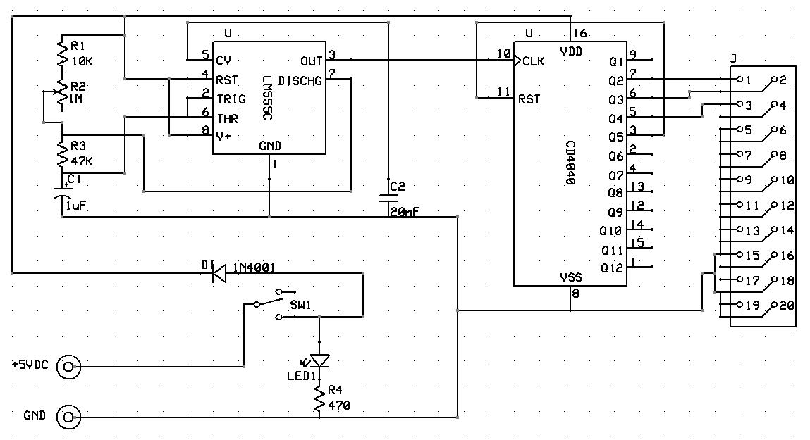
I adapted Leon's Zaccaria driver board test fixture with the following schematic:
Rather than having individual toggle switches, this one just continuously cycles through the three address pins and ties all of the chip select pins Low so as to continuously toggle all output pins of the Driver board for easy testing with a logic probe.
Most of the parts used by MrGame are either common, or were common at one time and are well known. Most have cross referenced parts that can replace them if you cannot locate the exact replacement. I have been able to find replacement parts for almost everything I have needed via Jameco, Mouser, or Halted Specialties.
When removing failed or corroded components, always cut the component off the board with a set of dikes. If it is a chip, cut the legs and pull the chip body off. Use a small hemostat to grasp the remaining leg while desoldering it from the back. Be careful to apply enough heat to melt the solder and release the leg, do not pull hard or the trace will pull off of the board.
There are now several good sources for ROMs for MrGame games. In addition to this web site, they are on Federico Croci's web site, The Internet Pinball Database, Leon's web site, and the host for the Visual Pinball pinball emulation software. If you have an image or a game for which images are not listed here on this web site, please email me and I will see to it that it is distributed to the other sites.
The most common failures I have seen are the battery leakage on the CPU board, Molex connector failure, especially CN1 on the power supply due to overheating, and corroded or failed fuse clips on the power supply board.