To make it easier to work on these boards on the workbench, instead of having to put them in a game to test them, it is possible to use a standard PC power supply and a few test jigs to test and diagnose them. The displays need high voltage (approximately 170VDC), but the rest of the boards only need +5V, -5V, +12V, and Ground. Leon's web site http://www.flipper-pinball-fan.be has several documents on it on doing this.
By interconnecting the boards with their ribbon cables, it is possible to run the game entirely on the bench. Unfortunatly, there will be no displays, so it is hard to test completely. But, a logic probe on the switch row connector (CN11) should show the matrix being scanned. Using a diode and a test lead, it is possible to enter the game diagnostics, and advance through the display test, solenoid test, lamp test, switch test, and sound board tests. For the solenoid, lamp, and switch tests, a logic probe should be used to show the lines on the driver board being grounded. For the sound board test, connect a 4 Ohm speaker with a 47 Ohm resistor in series to CN16 Pins 5 and 6 and the sound board tests should work. Note: if you connect a speaker, without the resistor in series, you will instantly destroy the TDA1510 amplifier IC. This part is hard to find, and expensive to replace.
Leon has added Zaccaria CPU and Driver board diagnostic tools, procedures and a test software EPROM to his web site at http://www.flipper-pinball-fan.be. If you have a CPU board that will not boot, or need to test a Driver board by itself, Leon can help.
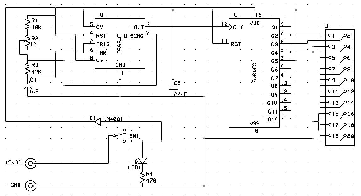
I adapted Leon's driver board test fixture with the following schematic:
Rather than having individual toggle switches, this one just continuously cycles through the three address pins and ties all of the chip select pins Low so as to continuously toggle all output pins of the Driver board for easy testing with a logic probe.
In order to test individual sounds, rather than having to wait for the game to cycle through all 64 of the possible sound / speech calls, I made a test jig that can be set to trigger one sound:
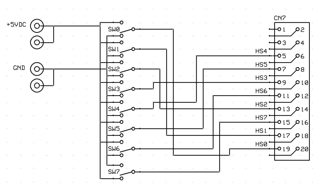
Use single pole double throw toggle switches for SW0...SW6. Use a single pole double throw momentary contact switch for SW7. Set the desired sound number (see the Farfalla sound map for examples) on SW0...SW6, then press the momentary SW7 to toggle the IRQ line. The corresponding sound or speech call should be played.
Most of the parts used by Zaccaria are either common, or were common at one time and are well known. Most have cross referenced parts that can replace them if you cannot locate the exact replacement. I have been able to find replacement parts for almost everything I have needed via Jameco, Mouser, or Halted Specialties.
The tricky part of working on a Zaccaria board is that the traces seem particularly easy to lift if too much heat is applied or the iron left in contact with the board for too long. This can be especially bad if there is any corrosion on the solder joints keeping them from melting easily and quickly.
When removing failed or corroded components, always cut the component off the board with a set of dikes. If it is a chip, cut the legs and pull the chip body off. Use a small hemostat to grasp the remaining leg while desoldering it from the back. Be careful to apply enough heat to melt the solder and release the leg, do not pull hard or the trace will pull off of the board.
There are now several good sources for ROMs for Zaccaria games. In addition to this web site, they are on Federico Croci's web site, The Internet Pinball Database, Leon's web site, and the host for the Visual Pinball pinball emulation software. If you have an image or a game for which images are not listed here on this web site, please email me and I will see to it that it is distributed to the other sites.
The most common failures I have seen are the battery leakage on the CPU board, Molex connector failure, especially CN1 on the power supply due to overheating, corroded or failed fuse clips on the power supply board, and cracked solder joints on the 7-digit display boards.
The next most common item is for IC38 on the CPU board, a 3081 transistor array, to fail. This IC is responsible for the switch matrix, so when it fails the game can have many strange symptoms as it sees various phantom switch closures. This is particularly common on games like Magic Castle and Farfalla that mount a high-voltage End of Stroke switch on the flipper mechanism, and stack a low-voltage switch matrix switch on it. If these two switches are accidently shorted together (like if somebody trys to adjust the switch gap with the power on), the result will be a dead 3081.
If you have recently repaired the boards, or have a game where the battery is dead or has been removed, you will need to go through and set up the game. If you are powering up an unknown condition game for the first time, see here first before continuing with the initial setup.
First, install the boards in the backbox with the interconnect cables. There should be 4mm mounting screws for all of the boards, 4 for the CPU, 4 for the Driver, 4 for the Power Supply, and 2 for the Sound board. If any are missing, you should be able to get replacments at a local hardware store.
Power up the game and check for smoke. If there is any sign of anything going wrong, power off immediately.
Assuming nothing blew up, you're ready to test and set up the game. Locate the DIP switch block (SW1) on the CPU board and change switch #4 to "on". The game will start going "Bing! Bing! Bing! Bing!...", this is normal. Open the coin door and press the Advance switch forward to get in to the game test and setup options. The noise should stop and you should be in the displays test (#1).
The displays will be cycling 0000000, 1111111, ... 9999999. If you press the Start button, they will start rolling 1,234,567 right to left as a second test. Confirm that all of your displays are working correctly. If you are missing any digits on any of the displays, check the solder joints on the display board where the pins from the glass are attached.
Press the Advance switch again to get to the Switch Matrix test (#2). With the ball removed and all of the drop target banks reset, you should have nothing displayed in the Ball/Credit display. Hopefully you have the manual and can verify that all of the switches are working correctly. If not, at least press each switch with a finger and make sure that something shows up in the display.
Press Advance again to get to the Controlled Lamps test (#3). All of the General Illumination lights are already on, and now the Controlled lamps should all be flashing. Note any that are not and replace them as needed.
Press Advance again to get to the Solenoids test (#4). Again, the manual is helpful here so you can tell if all of the solenoids are working correctly, but the game will cycle through all of them. A couple are "not used", so don't be alarmed by it skipping over a couple without anything happening.
Press Advance again to get to the last test, the Sound Board test (#5). All of the various game sounds and voice samples should be played.
Assuming you found no problems with the tests, it's time to set up the game for play. Zaccaria is a bit wierd, I think, in that the first time you power up the game, the CMOS contains random garbage. Rather than assume it to be bad and clear it, they just try to use it as though it were correct data. You absolutely must go through all of the Audits and game settings options and change them, even if they appear to be correct. If you, for example, look at option #10 (High Score Type) and you want it to be set to 0, you may find that when you get to #10 that the Ball/Credit display says that it is set to 0. Don't believe it, use the Start button to cycle through all possible values to get back to 0.
Press Advance to get from the Sound Board test to the Audits. The Ball/Credit display will show that you are in item #6. The Player displays will have random garbage. Press and hold the Start button to clear the first four Audits to 0.
Press Advance again to get to item #7, then press and hold Start to clear the audit data. Repeat for #8 and #9.
Press Advance again to get to the Operator Settings options. Items #10 through #37 are the game setup options. These are game specific.
Recommended operator settings for:
Be sure to set all of the options, even if they appear to already be set correctly. Keep pressing Advance to get to the next option, and Start to set the value, until you get to item #37.
When you get to #37, and have set the value to 0, press Advance one more time and the game will return to Game Over mode, and will resume it's "Bing! Bing! Bing! ..." noise. Change DIP switch #4 back to "off" and the game will stop complaining and be ready to play. Trip the coin switch to add a credit, and hit Start. Zaccaria doesn't have a Free Play setting option, so in the game options, you can set the first Replay score to a minimum value like 10,000 points, so the game will always have credits available on it.
If you have one of Zaccaria's games, and can transcribe the operator's settings for me from the manual, please email me: and let me know. I would like to include them here for other games.
There are two diagnostics LEDs on the boards in the backbox. Unlike more modern games, Zaccaria's LEDs don't tell you much about the game when you turn it on.
When you turn the game on, the LEDs in the backbox should:
| CPU | Sound |
|---|---|
| flicker | off |
| off | on |
| on | off |
Commonly, on a board where the battery has leaked, the CPU will attempt to boot, you will see the LED come on, then the game will crash and the LED will go out again. This is usually caused by either (or both) IC4 or IC5 being destroyed by the battery alkaline.
If you have just acquired a Zaccaria game in unknown condition and are powering it up for the first time, you should make several basic safety checks before hitting the power switch. This is to ensure your own safety and that of the game, and will only take a few minutes if there are no problems found.
First, CHECK THE FUSES. Only a fool overfuses a game, but there are a lot of fools out there. You may find 20A or 30A fuses where there should be something much smaller, just because the correct fuse blew. Remove each fuse and verify that it is the correct rating and type (Normal or Slo Blo). Replace any fuses that are over the rating found in the manual for the game.
Fuse locations and ratings:
| Fuse | Location | Rating | Type |
|---|---|---|---|
| Transformer (Front) | 5A | Normal | |
| Transformer (Rear) | 20A | Normal | |
| F1 | Power Supply Board | 1A | Normal |
| F2 | Power Supply Board | 5A | Normal |
| F3 | Power Supply Board | 15A | Normal |
| F4 | Power Supply Board | 1A | Normal |
| F5 | Power Supply Board | 5A | Normal |
| Under Playfield | 2 x 3A | Normal |
The Transformer fuse is located in the input voltage adjustment. Unscrew the knob on the front right uppper corner until it comes off. You will see the 5A line fuse, in addition to the settings for the supported input voltages (100V, 115V, 200V, 220V, 245V). The brass spike (and the window on the edge of the cover) point to the desired input voltage setting.
There are two fuses under the playfield in a small holder. They are both 3A fuses. Some games, like Farfalla, may have additional fuses in holders under the playfield; check these as well.
Once you have verified that the fuses are correct, check to see that the transformer in the bottom cabinet has been configured for the correct line voltage for your location. If the game was purchased locally, it most likely is already set correctly, but it doesn't hurt to double check it, and you have to open this up to check the line fuse anyway. If you are especially paranoid, you can verify that the transformer is putting out correct voltages.
First, with only CN1 connected to the Power Supply, and with all of the other connectors on the Power Supply disconnected, turn on the game, and use a meter to check the voltage test points on the Power Supply. Turn the power off again before continuing.
Second, disconnect the ribbon cables from the CPU board that lead to the Driver Board, Sound Board, and Displays. Also disconnect the Power Supply connectors CN2, CN3, CN4 as well as CN16 on the Driver and CN6 on the Sound board. Then disconnect the switch matrix, CN10 and CN11 from the CPU board. This leaves only the transformer, Power Supply (via CN1) and CPU board connected.
Turn the power on and watch the LED on the CPU. As described above, it should flicker briefly, go dark, then come on and stay on. If it does, the CPU booted correctly. If it does not, something is wrong either on the Power Supply or CPU board and will have to be troubleshot and repaired.
If the CPU seems to be booting correctly, turn the power off and reconnect one subsystem at a time. After connecting each subsystem, turn the power on and verify that that part of the game is working correctly and that none of the magic smoke escaped from anything. You can reconnect subsystems in any order, but I prefer this order:
Use the game's own self tests for the displays, switch matrix, lamps, solenoids, and sounds to verify that everything is working. Once the game is booted and running, press the Advance switch on the coin door to start the diagnostics. Pressing Advance will advance to the next self-test. Pressing Return goes back to the previous test. There are 37 to step through, comprising Diagnostics, Audits, and Operator Settings. Pressing Advance will eventually bring you back to game-over. Advance is Switch 0, Return is Switch 1 in the switch matrix. You will need at least one working display in the Ball/Credit position (jumper as Display 5) to see what you are doing.
The displays will cycle 1111111, 2222222, ... 9999999. All digits and all segments should be working. Pressing the Start button (Switch 9) starts a rolling digits test where the displays will show 87,654,321, then 98,765,432, then 09,876,543, etc. scrolling the digits from left to right.
Press Advance again to reach the switch matrix test. Use the switch matrix chart (Games and Documentation) and/or the playfield switch location chart in the game's manual to verify that all playfield, coin door, and cabinet switches register correctly. Zaccaria's switch test display only shows the number of the highest number switch that is closed, which can be confusing at first, so work up from switch 01 and ensure that each switch registers in the test. If there is a problem with the switch matrix where multiple switches are being seen closed at the same time, you will be able to see multiple switch numbers flash by on the display very quickly. This usually indicates a blown 3081 transistory array at IC38 on the CPU board.
The switch matrix test can also be done on the bench without a playfield by substituting a simple jumper lead with a diode in series. Connect the anode (banded end) of the diode to Row 0...7 (CN10 pins 6, CN11 pins 2...7, CN11 pin 9) and use the cathode (non-banded end) as a probe on Column 0...7 (CN11 pins 10...17). By working through all possible switches (0...63), you can prove that the board is working, so any switch problems found must be on the playfield. See Games and Documentation for switch matrix charts.
Press Advance to reach the controlled lamps test. All playfield and backbox controlled lamps will cycle on and off.
Press Advance to reach the solenoids test. All playfield solenoids will be pulsed, one at a time, to verify that they all work. The current solenoid number will be displayed on the Ball/Credit display as the game walks through all of them. Use the solenoid location page in the manual to verify that all are working. Not all games use all possible solenoids, and they were not necessarily all used in order, so it may be ok if it skips one or two. Verify against the manual to be sure. Some games use "solenoid" drivers for non-solenoid applications like the small playfield "Extra Kicks" display on Soccer Kings and the backbox chanse lights on Time Machine.
Press Advance to reach the sound test. All sounds and speech calls used by the game will be played, one at a time, with the current sound number displayed.
Use Advance or Return to return to Game Over.
When I first got my Farfalla, the ball plunger was bent. I replaced it with a generic Williams' black knob plunger, but it never looked quite right. At a coin-op show, I found a box full of Data East ball plungers from Laser War that had a nice translucent red knob, almost a perfect match for the original Zaccaria plunger. That looks much nicer than the generic black knob plunger.
The Yellow drop target bank on my Farfalla would never drop reliably when hit. Some targets were more prone to this than others, but even after a good cleaning, the ball would still sometimes just bounce off. I found that the problem was actually in the way that the plastic target is attached to the mechanism at the bottom. There is a cotter pin that holds the pivot pin in the bottom of the plastic drop target.
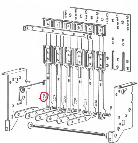
This pin is just close enough to the front metal wall of the target bank that the cotter pin can rub on the metal wall, even jam against it so that there is no way that the target can ever drop. I replaced the cotter pins with 7/32" E clips from the local hardware store, gaining the necessary clearance and now my drop targets always go down when hit. Pinball Champ '82 and Pinball Champ used a similar drop target bank with the targets extended to reach the upper playfield, so this probably applies to those games as well.
The microswitch in the outhole on my Magic Castle was broken when I got the game originally. I replaced it with a switch obtained from Mouser that is a perfect fit. Use part number 6115-V7-2B17D8-048, a long lever microswitch with a very low contact force rating. Mouser have other switches available that will fit, but with higher contact force ratings that do not work.
There is an error in the Electrical Power Wiring diagram included in the schematics package for Farfalla and Soccer Kings. Power Supply connector CN5 pins 3 and 4 are shown reversed, with CN5 pin 3 (GND) connected to Driver board CN16 pin 2 (5.6VCC), and with CN5 pin 4 (5.6VCC) connected to CN16 pin 1 (GND). The pins are labled correctly, just the lines connecting them on the schematic are incorrect. By the time Magic Castle was released, this error had been corrected. I don't (yet) know which game corrected it.
The moving playfield on Time Machine is controlled via a relay mounted under the playfield. Transistor Q (Q23) turns the relay on, which then starts the motor turning. The relay latches on via a runout switch mounted on a cam on the motor, which keeps the motor running until the cam allows the switch to open, disengaging the relay and stopping the motor.
On Farfalla, the solenoids used to reset the Yellow drop target bank have their own dedicated ground return, a Green/Yellow wire. This terminates in a female spade connector that connects to the cabinet ground strap via a male spade connector on the left wall of the backbox, just below the transformer for the neon lamp. This Green/Yellow wire, and its connection to the cabinet ground, does not seem to be shown anywhere in the manual or schematics for the game. If it is not connected, the Yellow drop target bank will not reset.
David Gersic
Copyright © 2001. All rights reserved.
This document may be freely distributed so long as the content is not modified.