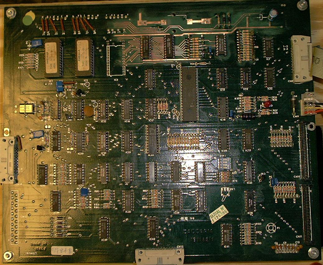
This board houses the CPU chip, game ROMs, game RAM, CMOS RAM with battery, and the circuitry for the switch matrix. It has connectors for power, switch matrix send/return lines, and ribbon cables to the driver, sound, and displays. Unlike most other solid state pinball manufacturers, Zaccaria used a Signetics 2650A CPU chip for their boards.
Click on the thumbnail above for a larger picture of a Zaccaria CPU board. This one has already had the (leaking) battery removed and the damaged area cleaned and neutralized.
The major areas of this board are:
| Pin | Voltage |
|---|---|
| 1 | 170VDC |
| 2 | Ground |
| 3 | Power Good |
| 4 | 5VDC |
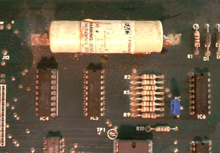
The biggest worry with a Zaccaria CPU board is the NiCd battery pack used to maintain the CMOS memory when the game is powered off. This battery pack is mounted at the top of the circuit board, in the center. If it starts to leak, the battery fluid runs down the board and ruins every component in its path. Click on the image above for a close-up look at the damage this does. Note the corrosion damage around the legs of IC4, IC5, and IC6, and around the legs of R2...R9. If you have a non-working Zaccaria game, this is the first thing to look for. If yours is working and hasn't leaked, PLEASE get the battery off the board and mount a remote battery immediately. If the battery has leaked, Clay's web site has a good recovery procedure for dealing with the corrosion and damage. After cleaning up and neutralizing the leaked fluid, remove and replace all components that were touched by the battery fluid, and all sockets on the board. Inspect the connectors and ribbon cables for signs of corrosion and replace as necessary.
To replace the original battery, a 1F 5.5V computer memory backup capacitor like Jameco P/N 142957 or Mouser P/N 555-1.0Z5.5 can be mounted on the CPU board in place of the battery pack and short leads used to connect it to the battery (+) and (-) traces, or a fly lead can be connected where the battery used to be and used to reach a remote battery pack.
To mount a remote battery pack, cut two wires to about 16" long, and solder them to the battery (+) and (-) pads. The other end I solder to a .100" two-pin connector snipped from an old PC floppy drive controller. I add a drop of JB Weld two part epoxy, then heat-shrink the connector, forming a small plug that is just the right size to connect a Radio Shack rechargable portable phone battery (Part #23-197, 3.6V, 350mAh, NiCad). Mount the battery on the left wall of the backbox with a velcro strap stapled to the wood, and you should never have to worry about battery leakage again. Replace the battery every few years, just to be on the safe side.
There are several logic test points on the CPU board:
| Test Point | Signal | Purpose |
|---|---|---|
| TP1 | HIGH | CPU Pin 1 - SENSE |
| TP2 | Pulsing | CPU Pin 38 - CLOCK |
| TP3 | Pulsing | Interrupt Generator |
| TP4 | LOW | CPU Pin 16 - RESET |
| TP5 | HIGH / Pulsing | CPU Pin 17 - INTREQ |
| TP6 | Pulsing | Out Counter |
| TP7 | LOW | Out Counter |
| TP8 | LOW | Voltage Good |
| TP9 | LOW / Pulsing | Clock oscilator output |
These are useful if the game is not running, or to confirm that it is running with the displays disconnected.
Three revisions of Zaccaria CPU boards for the games are covered by this document; part numbers 1B1165/0, 1B1165/1 and 1B1165/2. The differences between the 1B1165/0 and 1B1165/1 are minor, but potentially important. The 1B1165/0 board mounting holes at the corners of the board are insulated. This keeps them from grounding the board to the metal backplane of the game. Sand off the solder mask around the holes to ground the board. The other change is that the 3081 chips at IC34 and IC38 do not have pin 5 connected to anything. In normal operation in the game, this does not seem to matter, but it does lead to strange results when using Leon's test ROM. Make the 1B1165/0 like the 1B1165/1 by connecting pin 5 to pin 15 on these two ICs. On the 1B1165/1, this is accomplished by a trace hiding under the chip itself. This has no effect on the game, but will make Leon's test ROM code work correctly on the outputs through these two ICs.
On the 1B1165/0 and 1B1165/1 boards, as used in Farfalla, Pinball Champ, and Devil Riders, IC8 Pin 14 is connected to R26, IC9 Pin 39, IC10 Pin 16, and IC11 Pin 16.
On the newer 1B1165/2 board, as used in Magic Castle and all of the games after that, they added a jumper pad labled "J16" with options "E" and "F" on the board just to the right of IC8 Pin 14.
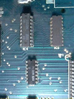 | 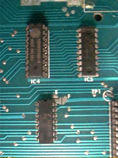 | |
| 1B1165/0 Board: Shows IC8, IC4, and IC5 | 1B1165/2 Board: Shows IC8, Ic4, and IC5. Note Jumper Pad J16. |
The options connect IC8 Pin 14 to either "E" or "F". If connected to "E", IC8 Pin 14 is connected to a trace that runs to IC4 Pin 18, then to R1, D1, and D2. Jumper "F" appears designed to make the 1B1165/2 board backward compatible with a 1B1165/0 or 1B1165/1 board, and IC8 Pin 14 is connected as described above to R26, IC9, IC10, and IC11.
This change, which powers IC8 from the Battery voltage that backs up the IC4 CMOS Static RAM chip is a memory protection circuit. Its purpose is to ensure that the Static RAM is deselected during power up, power down, and any power failure or lower power conditions. This keeps possible random signals on the address and data busses from being considered valid and corrupting the contents of IC4.
For this to work without prematurely draining the battery, IC8 must be a CMOS 74HC00, not a 74LS00.
For boards with the "J16" jumper, IC8 should be a 74HC00 and the board should be jumpered with J16 on the "E" side. If a 74LS00 is installed, connect the "F" jumper instead. While this memory protection circuit sounds good, I have yet to see a game with a 1B1165/0 or 1B1165/1 lose or corrupt its IC4 contents. The important part is to make sure that IC8 is a CMOS part if J16 is set to "E" to keep from draining the battery.
I have not seen many Signetics 2650 failures, even on badly corroded boards (the socket tends to protect the chip by being destroyed first), but have run in to CPU boards that were missing this chip. Replacements for this chip are scarce, but available. Note that Signetics made two processors, the 2650 and the 2650A. The 2650 runs at a slower clock speed than the 2650A. Zaccaria games require the faster 2650A processor chip. These were also used in some early home gaming consoles like the Emerson Arcadia 2001.