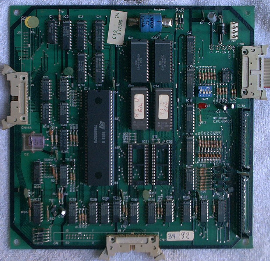
This board houses the CPU chip, game ROMs, game and CMOS RAM with battery backup, and the circuitry for the switch matrix. It has connectors for power, switch matrix send/return lines, and ribbon cables to the driver, sound, and video game board. Unlike the previous Zaccaria games, MrGame uses a Motorola 68000 CPU as the basis for these games.
Click on the thumbnail above for a larger picture of a MrGame CPU board. This one still has the battery mounted, again in the top centre of the board, where it can do the most possible damage when it leaks. GET THE NiCad BATTERY OFF YOUR CPU BOARD BEFORE IT LEAKS. This one was removed right after this picture was taken.
The major areas of this board are:
| Pin | Voltage |
|---|---|
| 2 | Ground |
| 3 | Power Good |
| 4 | 5VDC |
The biggest worry with a MrGame CPU board is the NiCd battery pack used to maintain the CMOS memory when the game is powered off. This battery pack is mounted at the top of the circuit board, in the center. If it starts to leak, the battery fluid runs down the board and ruins every component in its path. If yours is working and hasn't leaked, PLEASE get the battery off the board and mount a 5V 1F memory backup capacitor or a remote battery immediately. If the battery has leaked, Clay's web site has a good recovery procedure for dealing with the corrosion and damage. After cleaning up and neutralizing the leaked fluid, remove and replace all components that were touched by the battery fluid, and all sockets on the board. Inspect the connectors and ribbon cables for signs of corrosion and replace as necessary.
To replace the original battery, a 1F 5.5V computer memory backup capacitor like Jameco P/N 142957 or Mouser P/N 555-1.0Z5.5 can be mounted on the CPU board in place of the battery pack and short leads used to connect it to the battery (+) and (-) traces, or a fly lead can be connected where the battery used to be and used to reach a remote battery pack.
To mount a remote battery pack, cut two wires to about 16" long, and solder them to the battery (+) and (-) pads. The other end I solder to a .100" two-pin connector snipped from an old PC floppy drive controller. I add a drop of JB Weld two part epoxy, then heat-shrink the connector, forming a small plug that is just the right size to connect a Radio Shack rechargable portable phone battery (Part #23-197, 3.6V, 350mAh, NiCad). Mount the battery on the bottom of the cabinet with a velcro strap stapled to the wood, and you should never have to worry about battery leakage again. Replace the battery every few years, just to be on the safe side.
On the CPU, there's a "+12" test point, which is actually NOT a +12, but is, in fact, Ground. The back side of the board has the pins of CN9 that are labled +12 and Gnd bridged together, and the trace that would have been +12VDC is now being used as a Ground instead. The +12 from the power supply is not connected to the CPU board. This looks like a factory modification.