To make it easier to work on these boards on the workbench, instead of having to put them in a game to test them, it is possible to use a standard PC power supply and a few test jigs to test and diagnose them. The displays need high voltage (approximately 170VDC), but the rest of the boards only need +5V, -5V, +12V, and Ground. Leon's web site http://www.flipper-pinball-fan.be has several documents on it on doing this. The use of 2708 EPROMs on these does make it a bit more difficult to do this than on some other games.
These two boards are functionally very similar, and the same methods work on both. The only difference is that the 1B1146/2 has the ability to play a backround sound used on Locomotion. Both feature an 8035 microprocessor that runs independantly from the main game CPU, but under its control. That makes it possible to simulate the commands that would normally be sent by the game CPU to run the sound board independantly for bench testing and repairs.
Start by constructing a simple test jig to connect to the CN1 and CN2 connectors. CN1 supplies power to the board and has the speaker connection, while CN2 supplies the address, select, and data signals from the CPU:
| CN1 | |
|---|---|
| Pin | Signal |
| 8 | A0 |
| 7 | A1 |
| 10 | A2 |
| 11 | S3 |
| 1 | D0 |
| 4 | D1 |
| 3 | D2 |
| 6 | D3 |
| CN2 | |
| Pin | Voltage |
| 1/2 | 6.3VAC |
| 3 | +12VDC |
| 4 | GND |
| 5/6 | Speaker |
The Address, Select, and Data lines are all pulled High by pullup resistors on the board, and need to be pulled Low by the test jig. A Low signal is a "1".
Power up the board and check the two pins of the crystal with a 'scope or a logic probe. There should be a sine wave there. If not, the 8035 processor is likely to be bad. Jameco has replacements available.
To command the board to play a sound, load 0x06 on the Address lines (A0 High, A1 Low, A2 Low), then load a data value like 0x05 or 0x06 on the Data lines. Last, change the Select line from High to Low. This should cause the board to latch the Data lines via IC2 and play a sound. Then load 0xFF on the Data lines and change Select from High to Low again to clear the latch and prepare for the next sound call.
If no sound is played, the volume pot or the TDA1010 amplifier could be bad. Use a 'scope [1V 1mS] to probe R24 (1B1146) or R52 (1B1146/2) for the sound signal prior to it reaching the amplifier stage.
If the processor and ROM are good, you should also be able to use the built in self test loop to have the board play sounds continuously. DIP switch SW1 is connected to the processor interrupt line (INT) and turning it on will cause the board to being a sound test loop. The board will continue playing this loop until it is reset or power cycled.
By interconnecting the boards with their ribbon cables, it is possible to run the game entirely on the bench. Unfortunatly, there will be no displays unless you are using the game's power supply or have an alternate way to supply 170VDC to run them, so it is hard to test completely. But, a logic probe on the switch row connectors (CN8 / CN9) should show the matrix being scanned. Using a diode and a test lead, it is possible to enter the game diagnostics, and advance through the display test, solenoid test, lamp test, switch test, and sound board tests. For the solenoid, lamp, and switch tests, a logic probe should be used to show the lines on the driver board being grounded.
Leon has added Zaccaria CPU and Driver board diagnostic tools, procedures and a test software EPROM to his web site at http://www.flipper-pinball-fan.be. If you have a CPU board that will not boot, or need to test a Driver board by itself, Leon can help.
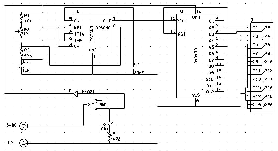
I adapted Leon's driver board test fixture with the following schematic:
Rather than having individual toggle switches, this one just continuously cycles through the three address pins and ties all of the chip select pins Low so as to continuously toggle all output pins of the Driver board for easy testing with a logic probe.
Most of the parts used by Zaccaria are either common, or were common at one time and are well known. Most have cross referenced parts that can replace them if you cannot locate the exact replacement. I have been able to find replacement parts for almost everything I have needed via Jameco, Mouser, or Halted Specialties.
The tricky part of working on a Zaccaria board is that the pads are small and the traces seem particularly easy to lift if too much heat is applied or the iron left in contact with the board for too long. This can be especially bad if there is any corrosion on the solder joints keeping them from melting easily and quickly.
When removing failed or corroded components, always cut the component off the board with a set of dikes. If it is a chip, cut the legs and pull the chip body off. Use a small hemostat to grasp the remaining leg while desoldering it from the back. Be careful to apply enough heat to melt the solder and release the leg, do not pull hard or the trace will pull off of the board.
There are now several good sources for ROMs for Zaccaria games. In addition to this web site, they are on Federico Croci's web site, The Internet Pinball Database, Leon's web site, and the host for the Visual Pinball pinball emulation software. If you have an image or a game for which images are not listed here on this web site, please email me and I will see to it that it is distributed to the other sites.
The most common failures I have seen are the battery leakage on the CPU board, and corroded or failed fuse clips on the power supply board, and dead 2-digit glass displays on the display boards.
The next most common item is for IC41 on the CPU board, a 3081 transistor array, to fail. This IC is responsible for the switch matrix, so when it fails the game can have many strange symptoms as it sees various phantom switch closures. It is also part of the processor reset circuit, which may keep the game from booting correctly.
It has been rare, but I have seen a couple of 5101 RAM failures where the game seems to boot and run fine, and may even pass Leon's RAM test (see below), but will still act flakey or strange. It may crash during a game, or score points that are not multiples of 10, or refuse to start a game despite there being credits available, etc.. The problems have been rectified by replacing the 5101 RAM. If you suspect that you are seeing this problem, swap the 5101 with a new one to see if it helps. Leon does have a version of his test ROM that runs the memory test continuously in a loop, which could also be used to diagnose this problem.
If you have just acquired a Zaccaria game in unknown condition and are powering it up for the first time, you should make several basic safety checks before hitting the power switch. This is to ensure your own safety and that of the game, and will only take a few minutes if there are no problems found.
First, CHECK THE FUSES. Only a fool overfuses a game, but there are a lot of fools out there. You may find 20A or 30A fuses where there should be something much smaller, just because the correct fuse blew. Remove each fuse and verify that it is the correct rating and type (Normal or Slo Blo). Replace any fuses that are over the rating found in the manual for the game.
Please note that there seems to be a significant variation in fuses between their first and last games in this generation. If at all possible, use the manual and schematics for the game you are working on, the silkscreen on the power supply board, or the printed cards stapled inside the machine to determine the correct fuse ratings. See the variations below the chart for specific game changes that I know of.
Fuse locations and ratings:
| Fuse | Location | Rating | Type | Note |
|---|---|---|---|---|
| Transformer board | 5A | Normal | ||
| Transformer board | 10A | Normal | ||
| Transformer board | 1.6A | Normal | ||
| Transformer board | 1.6A | Normal | 1 | |
| F1 | Power Supply Board | 1A | Normal | |
| F2 | Power Supply Board | 5A | Normal | |
| F3 | Power Supply Board | 15A | Normal | |
| F4 | Power Supply Board | 4A | Normal | 2 |
| F5 | Power Supply Board | 1A | Normal | |
| F6 | Power Supply Board | 1A | Normal | |
| F7 | Power Supply Board | 15A | Normal | |
| Under Playfield | 3A | Normal | 3 | |
| Under Playfield | 3A | Normal | 3 | |
| Under Playfield | 2A | Normal | 3 |
Fuse variations:
Once you have verified that the fuses are correct, check to see that the transformer in the bottom cabinet has been configured for the correct line voltage for your location. If the game was purchased locally, it most likely is already set correctly, but it doesn't hurt to double check it.
The power supply is the foundation for everything else, so on a game that is not working, it is usually best to start with the power supply. Assuming that the transformer has been jumpered to the correct input voltage setting, and the fuses have all been found, checked, and tested, start with the power supply.
The connectors used on these games are Amp MODU-1 parts, which seem to have held up better over the years than the .156" Molex square pin headers used on 2nd generation Zaccaria and many other pinball machines from other companies. Still, they can and do fail with time, heat, and stress, and can be broken, bent, or damaged by abuse. Check the connectors to ensure that the solder joints are not cracked, that the pins are not broken, bent, or tarnished from heat, and that the female mating connector is in good condition. Failed or missing connectors will have to be replaced, preferably with original parts whenever possible to preserve board interchangeability between games. If original parts are not available, then using standard Molex .156" parts will work so long as both sides of the connection are changed at the same time.
Once the connectors have been inspected and repaired if needed, then check the fuse clips for signs of corrosion or tarnish. These tend to weaken over time, with heat causing the spring metal they are made from to lose tension. This leads to bad connections, which tend to cause more heat, accelerating the failure of the clip. In all but the most unusual circumstances, I replace all fuse clips on the power supply board to ensure future reliability of the game. Use standard .25 inch PCB mounted fuse clips available from Jameco or Mouser, and drill the board as needed for them to fit.
Once the connectors and fuse clips have been dealt with, it is time to power up the power supply board by itself and see if it is working. Verify the input voltages at CN1 and the output voltages before continuing with the rest of the game.
Start with a visual check of the board, looking for any signs of trouble. Look first at the battery and surrounding area. Remove the battery immediately.. Look for signs of battery base corrosion on the pins and in the sockets for the ROMs, RAM, and processor, as well as signs of corrosion on the traces under the green solder mask. If you find any signs of corrosion, it must be cleaned up and neutralized. Use Clay's recovery procedure for dealing with the corrosion and damage.
While checking the board, pay close attention to any signs of previous repairs, as these can be a clue as to what has happened to the board in the past and what areas may need to be repaired, especially if the previous repairs were not well done. Keep an eye out for any missing parts or other obvious signs of damage. Replace, correct, or repair any of these you find before attempting to diagnose the board.
If the board looks good, you can go for the "Hail Mary" here and see if it will boot and run. Connect up the power supply, and one display, and turn the power on to see what happens. You may get lucky. If the board boots, it should detect that the stored settings data in the 5101 CMOS RAM chip is no longer valid, and should flash the displays alternating between 666666 and 999999 to let you know that it is running, but that it needs to be set up still. If you get this, there may still be problems to fix, but the board is basically working.
On a non-working board, there are several things that can be checked quickly and easily without having to dig deep in to diagnosing it that often can be a single simple problem that is keeping the board from working.
First, check the CLOCK circuit. This can be done with a logic probe, but an oscilloscope gives a better view of what is really going on. Put the probe on TP9 and look for a good clock signal:
 |
| (5V 1uS on a 100MHz 'scope) |
then check to see that it is making it all the way to the processor at pin 38.
Second, check the RESET circuit. This also can be done with a logic probe or an oscilloscope. Put the probe on TP6 and power up the board - look for LOW - quick HIGH pulse - LOW. There is only one pulse HIGH on this circuit, the designers assumed that only one would be needed and that the game would boot.
Assuming that the CLOCK is running, and that the RESET circuit works correctly, next double check that there are no breaks in the data or address bus traces. This is easiest to check using a digital meter with a continuity ("beep" or "tone") function. Put one lead on each pin of the data bus at the CPU, then check the corresponding pin on each of the ROM chips, then on the two RAM chips. Repeat this test for the address bus. Repair any broken traces and re-test before attempting any other diagnostics on the board. Once repaired, using either 'scope or logic probe, with the power on you should see activity on all address and data bus lines.
If the simple tests have not turned up the problem, then using Leon's test ROM (see http://www.flipper-pinball-fan.be) is next. Follow his procedures that go with the test software, and correct and re-test until the board passes all three of his tests before trying the game ROMs again. I have seen more failures of RAM than of either the input or output sections of these boards, so often do his tests out of order. Once the board boots, and passes his RAM test, then I move on to the input/output tests. Once all of Leon's tests pass, the game should boot and run with the game software ROMs installed.
Use the game's own self tests for the displays, switch matrix, lamps, solenoids, and sounds to verify that everything is working. Once the game is booted and running, press the Advance button on the coin door to start the diagnostics. Pressing Advance will advance to the next self-test. Pressing Advance will eventually bring you back to game-over.
The first time Advance is pressed, the game displays a summary of the operator audits.
The displays will cycle 111111, 222222, ... 999999. All digits and all segments should be working.
Press Advance again to reach the switch matrix test. Use the switch matrix chart (Games and Documentation) and/or the playfield switch location chart in the game's manual to verify that all playfield, coin door, and cabinet switches register correctly. Zaccaria's switch test display only shows the number of the highest number switch that is closed, which can be confusing at first. The 1st Generation switch matrix test leaves the last switch number on the display, as well. So work up from switch 01 and ensure that each switch registers in the test.
The switch matrix test can also be done on the bench without a playfield by substituting a simple jumper lead with a diode in series. Connect the anode (banded end) of the diode to Row 0...5 (CN9 pins 1...6) and use the cathode (non-banded end) as a probe on Column 0...7 (CN9 pins 10...17). By working through all possible switches (most games used switches 01...47, though some used less), you can prove that the board is working, so any switch problems found must be on the playfield. See Games and Documentation for switch matrix charts.
Press Advance to reach the controlled lamps test. All playfield and backbox controlled lamps will cycle on and off.
Press Advance to reach the solenoids test. All playfield solenoids will be pulsed, one at a time, to verify that they all work. The current solenoid number will be displayed on the Ball/Credit display as the game walks through all of them. Use the solenoid location page in the manual to verify that all are working. Not all games use all possible solenoids, and they were not necessarily all used in order, so it may be ok if it skips one or two. Verify against the manual to be sure.
Press Advance one last time and the game should return to Game Over.
Once the board boots and runs the game ROMs, it will need to be set up. Zaccaria 1st Generation games do not have any built-in software default settings to work with, they assume that the settings data in CMOS is correct and will use it. If the data in CMOS is incorrect, the game will boot, but will have no idea what to do next. It will cycle the displays between 666666 and 999999 and may make a sound effect to alert the operator that something must be done.
There are two buttons required to enter the game settings and audits. First, push the button on the CPU board. This memory protection ensures that only somebody with a key to open the backbox can enter the game audits and settings. After pushing the CPU board button, push the Advance button on the coin door. The Ball / Credit display should now show a "06". This is the first of the game settings. (01...05 are the self tests, accessed via the Advance button but without pressing the CPU board button first).
The settings are covered under the Games and Documentation page. For each setting, use the game Start button to change the current setting, and the Advance button to go on to the next setting. It is important to actually change each and every setting, to ensure that no stray garbage values in CMOS are left behind. On reaching the end of the settings, the operator audit data will be displayed, and the audits can be cleared by pressing the Start button again.
It is uncommon, but possible for random garbage data in the 5101 CMOS to confuse the game so badly that it will not boot correctly. One of the first revisions to the CPU board (1B1110/0) added a "clear RAM" feature. By jumpering TP19 (Switch Matrix Row 1) connected to TP20 (Switch Matrix Column 0) and powering up the game, the contents of CMOS will be ignored (so the game will boot), and will be cleared. This can help if the battery is gone, or if the 5101 CMOS chip is flakey and keeping the game from booting. Not all of the 1st Generation games have this feature in the hardware and software, but it may help on a game that does support it.
The game software has no default settings, so if a game has no CMOS settings already on power up, either from a dead battery or from having had the memory cleared via the TP19/TP20 trick, it would be essentially dead on location since it will not take coins or allow games to be played. They solved this problem by adding the 1B1149 settings board to some of the games. On start up, the games that support this board detect invalid CMOS contents, and use the dip switches located on this board (switch matrix rows 6 and 7) to establish default pricing and coin options so that the game will actually work on locaton instead of being dead.